Coordinate and Dimensional Shift of FBT UV Mapping in Blender
Case of Chandra Yudhistira Airbus A320 3D Model | DOCUMENTATION
Arya Yudhistira
4/24/20264 min read
COORDINATE SHIFT
The way Airbus A320 model is mapped is by dividing each UV map part in half with aligning edges. Upon assessing the alignment between left and right (LH, RH) fuselage UVs, the author discovered that the left fuselage UV stretched longer than its contrary by 5-10 pixels. Though this could be faulty at the painting stage, it could also be a sign of UV misalignment. An attempt to fix the issue by normal practice was to set an Alignment Adjustment layer (AAL). A defined line X is placed on a certain side of a determined decal, and line Y in other side serves to find the meeting point of both sides. The AAL is later obsolete once it has been figured that the issue is mostly emplacament rather than scale.
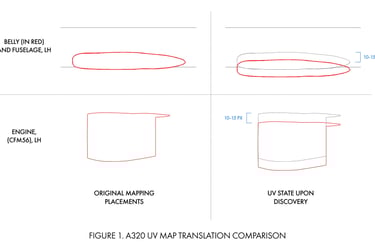
When the UV is assessed through the UV panel, it is discovered that Fuselage-Belly-Tail (FBT) as well as engine UV have been shifted, mostly by approximately 10-15 pixels in the Y-axis, as shown on Figure 1. A simple fix of remapping was conducted successfully. UV outlines were shown during this process to identify whether the UV and livery masking has aligned or not. This could be identified through checking whether a face, supposedly filled with a solid color other than white, is showing any other color than itself.
During this process, it is discovered that the LH belly UV mismatched the outline in Photoshop. The UV Kit outline includes portions of the fuselage UV to its area. Under normal eurowhite or solid white liveries, this could be easily dismissed. In the case of Pelita Air, the second scheme which features red curves from the top to the bottom fuselage does exclude the belly. This is a rare, but normal practice (see PK-GUG). Portions of Pelita red spilled into the belly, resulting in an imbalance. This should not happen, as fuselage and tail UVs are projected correctly and proportionally.
The reason behind these shifts is various. A simple Blender error when writing the UV map or identifying declared mesh selections could produce incorrect boundaries. On the other hand, incorrectly sorting UVs to outlines could mix up 2D side-view references, UV maps, and other outlines. Using 2D side view references for outline will result in incorrect reading, as there will still be contrast from 2D illustration to 3D meshes. These factors, combined with mostly white liveries, left the belly section unsupervised as the section would usually be in either full color or full white.
Upon generating base texture UV Maps, it is initial to set a canvas through Image > New. After defining a canvas, select at least one mesh, define which parameters are included (which is usually whole or half the mesh), and use “project from view”. The projected geometry may come in deformed dimensions that must be corrected, either manually or by supplementing Add-ons. The latter step provided an enforcing reason for 2D-3D integration. 2D side-view illustrations are used to generate a reference on how the deformed dimensions should be. This dates back to setting 4 axis reference planes using 2D references for right and left orthographic views in the beginning of modelling.
DIMENSION SHIFT
Upon exporting a UV Map (UV > Export UV Layout), the target file is set to .png at 0.25 fill opacity (editable). This process, combined with several groups of FBT UVs, is shown as gray on the .png. It is then converted to black strokes with no fill using the selection tool. The belly projection is done in sync with fuselage and tail sections. Later in Photoshop, the dimensions might once again come in distorted. To this stage, the 2D illustration will adjust. Though meshes could be reprojected over and over again (indestructive), it would be inefficient for standarization when it comes to batches of livery and “one-click” workflow. Currently, all of the A320 texture is applied by only changing one texture file.
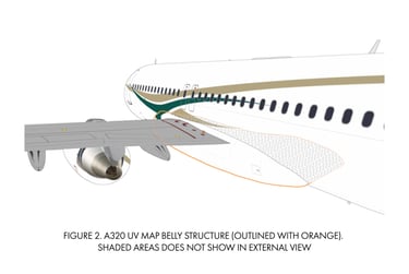
Figure 2 shows the structure of the belly section that continues inward to the fuselage. Being less time consuming, these inward sections (shaded in gray) does included to the final UV mapping. The belly modelling method is to start with a cylinder that is laid 90° perpendicular to the axis where the model faces (in this case, the X-axis). The cylinder is later incrementally scaled down in all axis as it nears every side of the belly. This method is deeming a more clean replacement, yet it requires complex surface modelling with harder control over curving and rounded topologies. The A320 belly requires constant adjustments of oval and curving seams to transition with the fuselage, which is difficult to be processed automatically inside Blender.
Post-mapping, the fuselage geometry is expected to “end” where the belly is supposed to extend. In this dimension shift, the projected dimension on the texture outline does not match the mesh geometry. This indicated (a) the fuselage took up a portion of the belly, or (b) the belly needs to be restretched. The belly was then resized by pinpointing a verified location which the author surely is accord, then put a 2D cursor to that point. After that, the section is scaled to match the appropriate dimension, which failed. Solution (a) was discovered by duplicating the RH FBT outline, flip horizontally, and layering it on top of the RH outline. It is discovered that LH FBT is scaled to be smaller than RH’s. A patching method is used by separating only the belly, erase the existing outline, and merge it to LH’s FBT layer. Outline checking was once again conducted to ensure that FBT sections were transitioning seamlessly.
Similar cases of dimensional shift occur in other UV projections. The author’s Boeing 737-800 model suffers the same when the tail and fuselage scale do not match on outline comparison. Both sides are projected with the same zoom level. For instance, RH FBT UVs are projected first, then left. LH FBT UVs followed. Both LH and RH UVs are distorted at the same dimension, same as they were user-corrected. During the transition to outlines, the shift reoccurred. A simple fix to this issue is to periodically monitor and patch UV shifts, as well as ensure that all UVs are uniform throughout the outlining process.